|
Schematics
Here is a BIG collection of Schematics.
Many thanks to BEAM-online
who , without him, I couldn't have bring you this wonderful page. To
build any of these circuit, you will need to know the pins layout of the
components. Click here to go to the pins
layout page.
All of the
shematics were made with Paint 
--------------------------The
page is under evolution-------------------------------
Solar engines ( SE )
- FLED
SE
-1381
SE
- LM3909
SE
- MILLER
SE
- variable
MILLER
SE
- Hyperpopper
Power SE
Photovores ( battery and solar power photovore )
- BEAM ant
- LM3909 photovore
- 1381 photovore
- FLED photovore
- Xvore from Wilf Rigter
Walkers
- Almost complete walker schematic
- 4 motors walker ( using 4 Bicores )
- 4 non modify servo motors walker ( ServoCore )
- Microcore
- Pulse Neutralisation Circuit ( PNC ) for Microcore
Bicore
- Suspend bicore
- Light seeking Bicore
Motor drivers
- H-bridge ( 6 transistors )
- Free form H-bridge ( 6 transistors )
- 74ALS245 motor drive
- Simple H-bridge BAL6686
Snake
- Bicore ( master-slave )
- ServoCore
- Master Salve Monocore
Complete
walker schematic
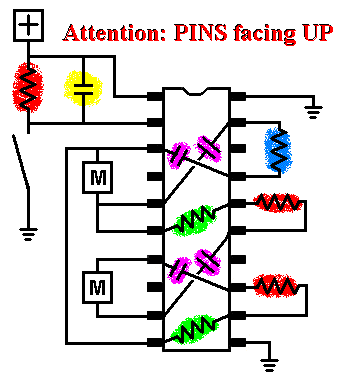
• 74HCT240
• 4 x .22 uF bi-polar capacitors (Violet)
• 30 uF capacitor (Yellow)
• 2 x 47K resistors (Green)
• 3 x 1.6M resistors (Red)
• 2.5M resistor (Blue)
• Motor drivers (H-bridge) + Geared motors (servos) (M)
• Tactile Sensor
Back
to top
4 motors
walker >CLICK on the image to see it BIGGER<
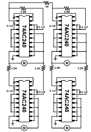
• 4 x 74HCT240
• 8 x 0.1uf capacitor ( read note )
• 4 x 2.2M resistor
• 2 x 4.3M resistor
• 1M resistor
• 4 x motors (servos motors)
The value of the capacitors can be different from a robot to a other.
It really depend of the type of motors you use. If you have a low RPM
( Rotation Per Minute ) ( turning slow ), you
need to but bigger value for the capacitors. But in the other hand, if
you have a high RPM ( turning fast ), you need to but
smaller value for the capacitors. You need to EXPERIMENT. It
won't kill you to try different resistors and capacitors value. You
will learn from you experiment.
If you want to put a reverser to the walker, put it where you see the R on the drawing
below.

I think you need to put a H-bridge to control the servos or motors.
Don't forget to check out the Scout
walker 2 from Solarbotics.
Back
to top
4 non-modify
servo walker
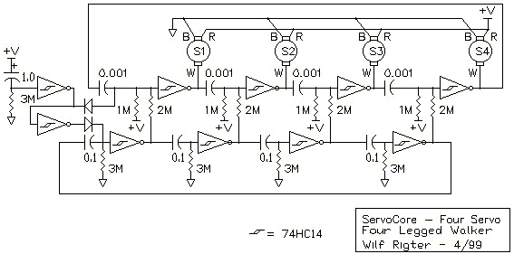
>CLICK on te image for
better quality.<
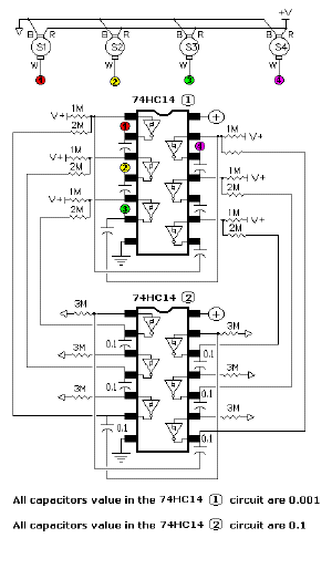
Back
to top
The
Microcore >CLICK on the image to see it BIGGER<
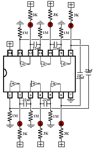
• All capacitors value are 0.22uf Bi-polar
• All resistors are 1 MegW
• Power from 3 Volts to 10 Volts
**Click Here for more information about the Microcore Circuit**
Back
to top
Auto PNC (Process Neutralization Circuit)
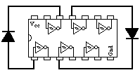
• 2 x diode 1N4148
You just add these two diodes to your microcore. When you power the microcore you will achieve the single process state.
Back
to top
Bicore
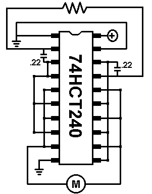

• 74HCT240
• 2 x .22uF bi-polar caps ( 224 on cap )
• 100K to 10M ohm resister the resistor goes between the two (R)
• Motor
• 3V
Back
to top
Phototropic Bicore
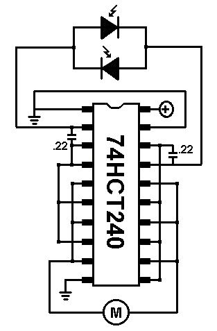
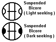
• 74HCT240
• 2 x .22uF bi-polar caps ( 224 on cap )
• 2 x Photodiodes
• Geared Motor (M)
• 3V
Back
to top
Free form H-bridge
• 2 x 100K or higher resistors
• 4 x NPN 2N3904 Transistors
• 2 x PNP 2N3906 Transistors
• Motor (M)
Back
to top
H-bridge
• 2 x 100K or higher resistors
• 4 x NPN 2N3904 Transistors
• 2 x PNP 2N3906 Transistors
• Motor (M)
Back
to top
Driver
• 2 x 74ALS245
You can stack chips to double the output current.
Back
to top
Simple motor driver
• BAL6686
**Chick here for more information**
Back
to top
Master Slave Monocore from Wilf Rigter
Back
to top
Robot Snake 1
Back
to top
Robot Snake 2
Back
to top
Back
to top
Back
to top
Back
to top
|
